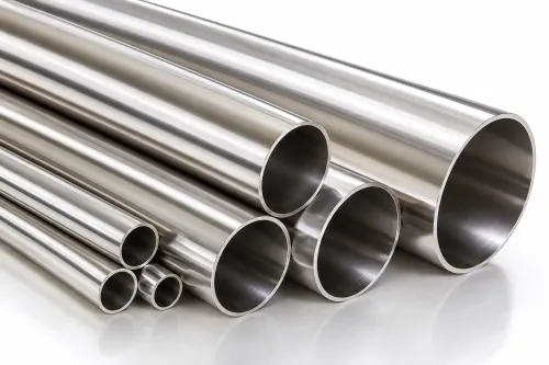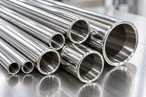
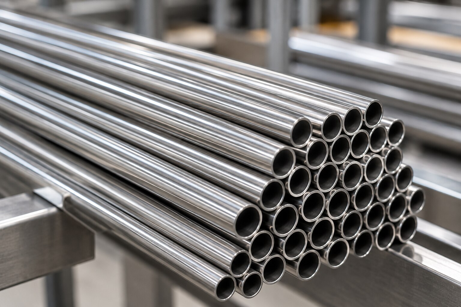
A tube that looks correct can still cause leaks, slow instrument response, poor bend performance, or premature corrosion when its outside diameter, wall thickness, alloy, hardness, or documentation does not match the installation. By the end, you will be able to turn the instrument connection and service conditions into a tube specification that covers dimensions, construction, material, finish, testing, and traceability.
Key takeaways
- Match tube outside diameter and wall thickness to the exact fitting.
- Choose annealed or hard tubing for the specified installation method.
- Select alloys for chloride exposure, temperature, acids, and welding conditions.
- Require material certificates, dimensions, surface finish, and pressure-test records.
Start with the Connection, Flow Path, and Pressure Design
Select an instrumentation tube by the connection’s exact tube outside diameter and wall thickness, then check the inside diameter against the required flow path. A 1/4-inch compression fitting needs 1/4-inch tubing; a nominally similar metric tube is not interchangeable.
Tube pressure design must cover material allowable stress, temperature, manufacturing tolerance, corrosion allowance, and the fitting assembly—not just a catalog rating for the tube. Compare allowable pressure with the governing piping code and fitting manufacturer’s rating. Apply these checks:
- For an instrument connection, match OD, wall thickness, fitting series, and manufacturer system; confirm the dimensional tolerance and ovality requirements for compression fittings. A mismatch can leak or fail to grip.
- For impulse-line sizing, calculate pressure drop using actual ID, run length, fluid viscosity, elevation, and required response. Reducing ID on a long liquid line can cause sluggish readings, liquid holdup, or plugging.
- For an analyzer line, size ID and length for analyzer-line response time. A smaller bore can delay gas arrival and distort the sample.
- For a control-system installation, reserve straight tube near fittings, the specified bend radius, supports, and vibration isolation. Mechanical loading at the instrument connection can cause fatigue below the pressure limit.
Treat metric versus inch tubing as separate systems.
| System | Selection rule | Consequence |
|---|---|---|
| Metric | Order the specified millimetre OD and wall thickness | 6 mm tubing is about 0.014 inch smaller than 1/4-inch tubing; a compression fitting cannot safely compensate |
| Inch | Order the specified fractional-inch OD and wall thickness | Do not substitute metric tube because the nominal size appears close |
Choose Construction and Hardness for the Installation Method
Choose seamless instrumentation tubing when a longitudinal weld would create an unacceptable discontinuity, cleanliness concern, or inspection burden. Choose welded instrumentation tubing when consistent dimensions, delivery length, and cost matter, provided the weld quality matches the service.
ASTM A269 does not identify construction by itself; state seamless or welded, heat treatment, dimensions, testing, surface requirements, and weld inspection in the order.
| Construction | Strength | Select it when |
|---|---|---|
| Seamless instrumentation tubing | Removes the longitudinal weld as a potential discontinuity | Pressure, cleanliness, or service consequences justify the added cost |
| Welded instrumentation tubing | Consistent dimensions and efficient production | The supplier provides controlled weld quality, suitable nondestructive testing, and traceable inspection records |
Condition controls how safely you can form the tube. Annealed tubing suits tight tube bending, flaring, and routing with multiple direction changes; it reduces cracking and ovality during forming. Hard-drawn tubing suits straighter runs with limited forming, but forcing it around a small radius can split the tube or overload the fitting.
Treat hard-drawn tubing and cold-worked tubing as different from the annealed starting condition: drawing, straightening, bending, and swaging raise hardness and residual stress.
Do not claim vibration resistance from hardness alone. Support spacing, bend radius, a straight section at the fitting, and isolation at the instrument control fatigue. Use double-ferrule compression fittings from one qualified fitting system, and avoid repeated assembly of a worked tube end. Mixing ferrules, nuts, bodies, or tube materials can change grip and make-up.
Select annealed tubing when frequent disassembly, flaring, or field rework is expected.
Match the Alloy to Chlorides, Heat, Acids, and Welding
Use 304/304L stainless steel for mild, clean environments; move to 316/316L stainless steel when chlorides or stronger corrosion exposure make its molybdenum content valuable.
| Grade | Chlorides, acids, and heat | Welding and service decision |
|---|---|---|
| 304/304L stainless steel | Suitable for many general process fluids, but more vulnerable to chloride pitting and crevice corrosion. | Choose 304L for low carbon welding where moderate temperature and corrosion conditions permit. |
| 316/316L stainless steel | Better localized chloride resistance than 304/304L and useful for many acidic services; it is not chloride-proof. | Choose 316L for low carbon welding, then remove heat tint and contamination from the weld zone. |
| 321 stainless steel | Choose for elevated temperature when titanium thermal stabilization is needed to resist sensitization after heating or welding. | Useful where repeated heat exposure makes an unstabilized grade a concern. |
| 347 stainless steel | Choose for elevated-temperature service where niobium stabilization and resistance to sensitization are preferred. | A strong option for welded, high-temperature components requiring stabilized material. |
Do not treat 316/316L stainless steel as protection against stagnant brine. Deposits, clamps, threaded cavities, evaporating droplets, high temperature, and narrow crevices can still initiate corrosion.
For sour service, qualify the complete material and environment under ISO 15156/NACE MR0175. Check hydrogen sulfide, temperature, chloride level, pH, tensile strength, hardness, heat treatment, and final cold work; the alloy name alone does not prove acceptance.
Specify the Standard, Finish, Tests, and Documents You Will Accept
Accept only a purchase specification that names the tube construction, grade, dimensions, tolerance, heat-treatment condition, surface finish, straightness, cleanliness, and test method. “ASTM A269” alone does not prove seamless supply or a suitable internal surface.
| Standard | What it covers | What to state or verify |
|---|---|---|
| ASTM A269/A269M or ASME SA269/A269M | General austenitic seamless or welded tubing | Seamless or welded, wall tolerance, annealing, finish, and pressure test |
| ASTM A632/A632M | Small-diameter seamless and welded tubing | Use when the bore is substantially smaller than conventional process tubing |
| ASTM A213/A213M or EN 10216-5 | Seamless heat-exchanger, boiler, or pressure-service tubing | Confirm the grade, dimensions, heat treatment, and test requirements |
| EN 10305-1 | Precision dimensional tubing | Confirm delivery condition, dimensional tolerances, and surface condition |
| ASTM A270/A270M | Sanitary tubing | Specify weld condition, drainability, roughness measurement, and cleaning compatibility |
Require an EN 10204 3.1 material certificate linking the chemical analysis and mechanical results to each heat number. Obtain dimensional inspection results for outside diameter, wall thickness, ovality, and straightness, plus a pressure-test record identifying test pressure, duration, medium, and acceptance result.
- For cleanliness, request cleaning records and define the allowable residue, packaging, and capped ends.
- For passivation, name the ASTM A380 cleaning procedure and ASTM A967 treatment, verification test, rinsing quality, and certificate. “Passivated” alone proves little.
- Ask SMD Impex to identify whether bright annealed, pickled, mechanically polished, electropolished, or passivated describes the surface finish; these terms are not interchangeable.
Related product
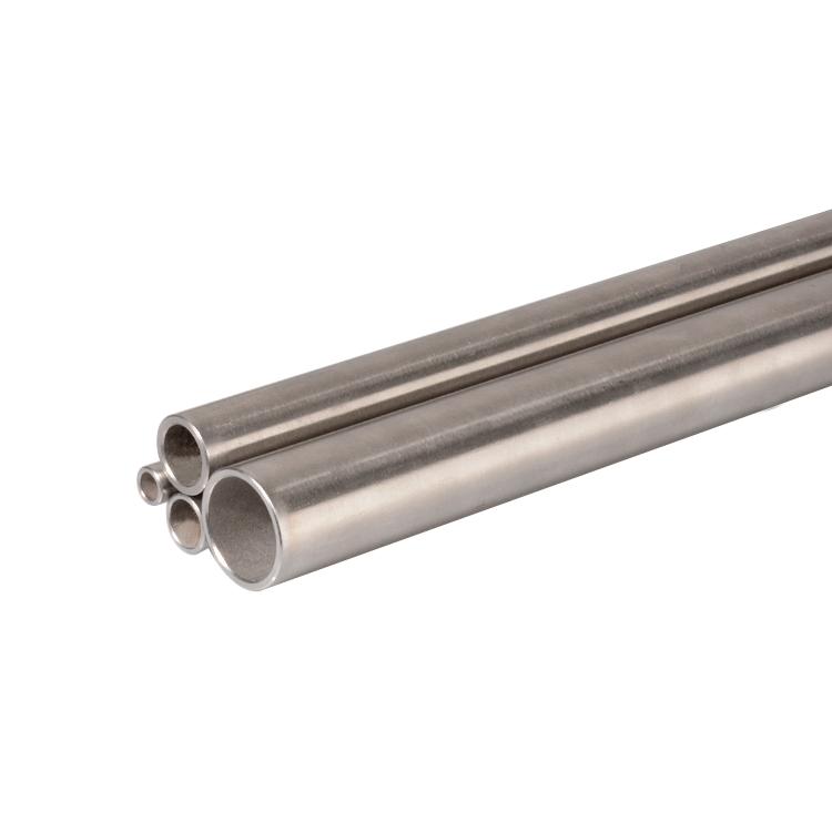 | Stainless Steel Instrumentation Tubes Stainless Steel Instrumentation Tubes High-Precision Tubing for Industrial Applications Stainless Steel Instrumentation Tubes Supplier in Vadodara Stainless Steel Instrumentation Tubes... View product → |
Control Installation Risks Before the Tube Reaches the Instrument
Reject or quarantine tubing with damaged ends, missing caps, mixed heat numbers, or visible dents before it enters the work area. A disciplined tube receiving inspection protects internal cleanliness and prevents an unidentified length from disappearing into a critical circuit.
1. Complete traceability and heat-number verification against the purchase order, material certificate, grade, outside diameter, wall thickness, and lot markings. Keep capped ends in place until preparation.
2. During routing, preserve the specified bend radius, support spacing, and minimum straight length beside each fitting. Add vibration isolation at instrument connections; unsupported spans and rigidly loaded fittings fatigue quickly.
3. For impulse-line installation, check actual inside diameter, run length, elevation, and fluid viscosity. An undersized line can trap liquid, plug, or delay pressure response; an analyzer sampling line needs enough flow to reach the analyzer without excessive transport time.
4. Cut squarely and perform deburring inside and outside. Remove chips and abrasive residue before assembly, then inspect the bore with clean light or a swab.
5. Use the fitting manufacturer’s matched body, nut, and ferrules. Follow its ferrule make-up procedure and record the final position; do not substitute parts because the thread and tube OD look identical.
6. Treat tube fitting reassembly as controlled work: inspect the grip and tube end, follow the specified remaking instructions, and replace damaged components. Repeated tightening does not restore a poorly prepared joint.
7. Finish with leak testing at the specified pressure and medium, then verify zero drift, purge flow, valve orientation, and signal response. Commissioning that ignores response time can leave a leak-free measurement unusable.
Frequently asked questions
How do you select the correct instrumentation tube size?
Match the tube outside diameter and wall thickness to the fitting and pressure design, then verify the inside diameter for the required flow path. A 1/4-inch compression fitting requires 1/4-inch tubing; a nominally similar metric tube is not interchangeable.
Should you choose annealed or hard stainless steel instrumentation tubing?
Choose construction and hardness based on the installation method. Consider whether the work requires bending, repeated routing, orbital welding, or direct connection to compression fittings.
Which stainless steel alloy is suitable for instrumentation tubing?
Match the alloy to chloride exposure, operating temperature, acid chemistry, and welding requirements. Compare grades such as 304, 316, and 316L against the actual service environment.
What should you specify when purchasing instrumentation tubes?
State the dimensional standard, surface finish, required tests, heat or batch traceability, material certificate, and documents you will accept before delivery.
How can you reduce installation risks in instrumentation tubing?
Protect tube ends, prevent contamination, use the correct cutting and deburring tools, inspect fittings, control bend radii, and test the completed line before connecting the instrument.