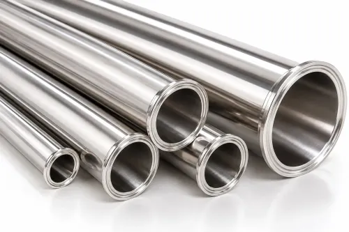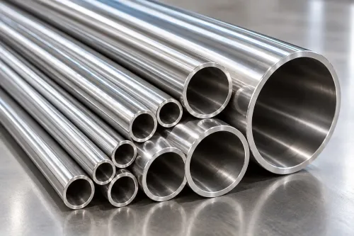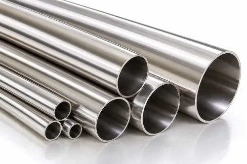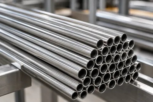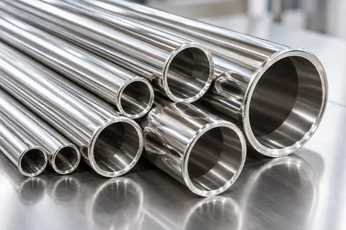
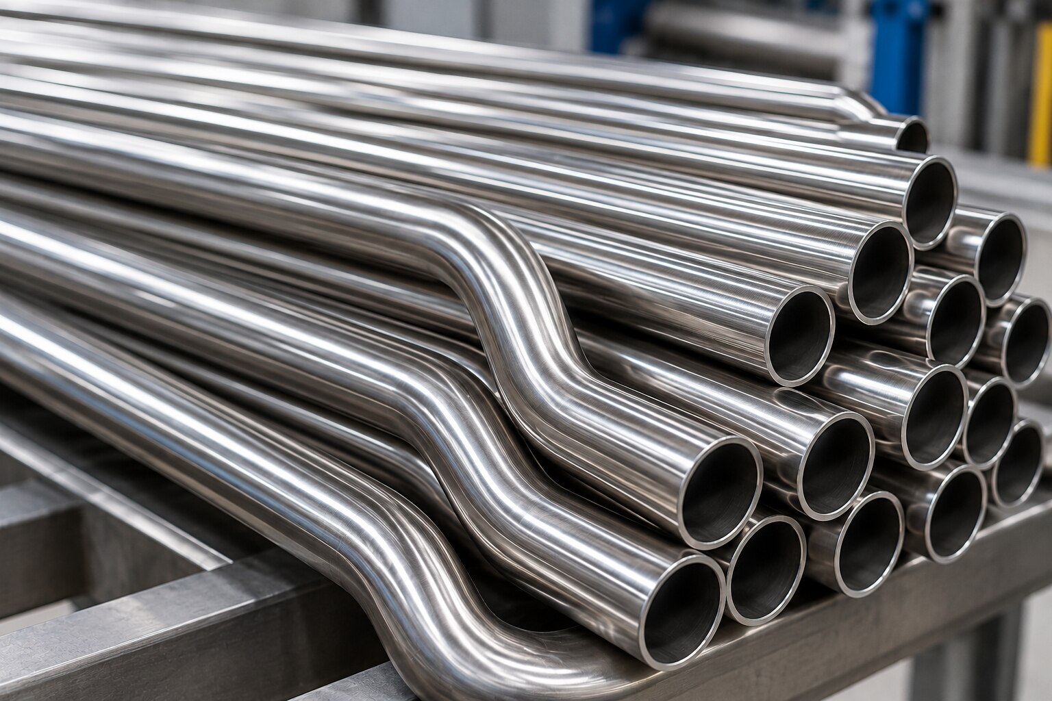
Hydraulic tubes form the fixed passages that move oil between pumps, valves, actuators, accumulators and reservoirs, but their suitability depends on more than stainless steel grade. By following the circuit path, pressure conditions, movement, connection system and manufacturing evidence, you can decide where rigid tube belongs and when hose or another material is the safer choice.
Key takeaways
- Use rigid tube for fixed runs; reserve hose for movement and vibration.
- Match tube pressure rating to working pressure, surge pressure and temperature.
- Specify tube OD, wall thickness, stainless grade, construction and end connections.
- Support and clean every run to control vibration, contamination and fatigue.
Where hydraulic tubes sit in a machine circuit
Stainless hydraulic tubes connect the power unit to directional-control valves, actuators, accumulators and the reservoir, creating fixed passages for pressurised oil. The pump raises fluid pressure, then pump outlet lines carry the oil to a valve manifold, where spool movement directs it to hydraulic cylinders or hydraulic motors.
| Circuit position | Connected equipment | What the fluid does |
|---|---|---|
| Pump outlet line | Pump, filter and valve manifold | Carries pressurised oil from the power unit to the control section |
| Actuator line | Directional-control valve and cylinder or motor | Delivers flow to create linear force or rotary torque |
| Accumulator branch | Valve manifold and accumulator | Stores pressurised fluid and releases it during peak demand |
| Return circuit | Valve, actuator and reservoir | Carries lower-pressure oil back for cooling, filtration and reuse |
| Lubrication circuit | Pump, metering valves and bearings | Supplies controlled flow to moving machine parts |
| Mobile-machine control line | Joystick valve, pilot valve and actuator | Transmits control pressure that positions the main valve or actuator |
A directional-control valve reverses or stops flow, so a cylinder extends, retracts or holds position; a motor changes speed or direction as flow and pressure change. The reservoir receives returning oil and supplies the pump again.
The tube carries fluid, not cleanliness by itself. Cutting chips, burrs, weld scale and oil can damage servo valves and pumps, so clean and flush the completed circuit to its specified ISO 4406 contamination code. Stainless steel earns its place where corrosion, washdown or external contamination makes carbon steel unsuitable.
When to use rigid tube instead of hydraulic hose
Use rigid hydraulic tube for fixed runs between firmly mounted components; choose hydraulic hose where movement, vibration, or frequent disconnection would otherwise load the line. The decision concerns motion and fatigue, not pressure alone or the use of stainless steel.
| Option | Rigid hydraulic tube | Hydraulic hose |
|---|---|---|
| Fixed geometry | Suits permanent, accurately supported routes | Suits components that move relative to one another |
| Vibration | Needs clamps, short unsupported spans, and isolation from pumps or motors | Absorbs movement but still needs abrasion and bend-radius control |
| Service access | Clean, compact, and durable after fabrication | Faster to replace or reroute |
| Pressure cycling | Handles steady service when the tube-and-fitting rating covers working and peak pressure | Requires a specified working-pressure, temperature, bend-radius, and impulse pressure rating |
Make the final choice with these checks:
- Select rigid hydraulic tube when the line can follow a stable route without forcing alignment between ports. It works well for fixed equipment connections where cleanliness, external corrosion resistance, and long service life matter.
- Select hydraulic hose at a cylinder, motor, or machine joint that travels, pivots, or transmits movement. Hose can isolate pump pulsation and vibration, but frame contact or a bend below the minimum radius causes early failure.
- Verify the complete assembly rating. The lowest-rated tube, fitting, valve, adapter, or hose limits working pressure; proof and burst pressure are not working-pressure values. Include supports, thermal movement, and replacement access in the layout.
How pressure, dimensions and stainless grades determine selection
Select the tube as a complete pressure boundary, not by stainless grade alone. Start with the circuit’s working pressure, peak pressure, fluid temperature and applicable design code. Proof pressure and burst pressure are test or failure thresholds, not allowable continuous pressure. The lowest-rated tube, fitting, valve, adapter or hose limits the assembly.
Specify exact outside diameter and wall thickness. Outside diameter must match the chosen compression, cone or flare fitting; a similar nominal pipe size will not fit, and inch and metric dimensions are not interchangeable. Choose wall thickness from the manufacturer’s pressure calculation, then check bend radius, ovality, flow restriction and fatigue life.
Temperature reduces allowable material stress.
- 304L: choose for general hydraulic service with low chloride exposure and moderate corrosion demands.
- 316L: choose for coastal, washdown or chloride-bearing environments; confirm the fluid and temperature remain compatible.
- Duplex stainless steel: choose when higher strength or chloride resistance justifies tighter welding and forming controls.
Ask for the tube-and-fitting pressure rating at operating temperature, the material certificate, dimensional tolerance and the governing standard, such as EN 10305-4 or ASTM A269. Confirm the selected grade, wall and outside diameter together; a stronger alloy cannot compensate for an undersized tube, incompatible fitting or poorly formed bend.
How to compare tube construction, fittings and supplier evidence
Do not select a seamless hydraulic tube solely because it has no weld. A correctly formed welded hydraulic tube can perform reliably when its seam quality, heat treatment, dimensional tolerances, nondestructive testing and pressure design basis are documented. Compare the completed tube-and-fitting system, not the word “seamless.”
| Option | Construction evidence | Main check |
|---|---|---|
| Seamless | Cold-drawn or cold-finished tube with specified wall tolerance and surface condition | Confirm allowable working pressure at temperature; seamless construction does not establish the rating |
| Welded | TIG or other specified weld process, with weld inspection and forming controls | Check seam integrity, ovality, weld-area finish and required pressure or leak testing |
ASTM A269 covers general-purpose seamless and welded austenitic tubing; EN 10305-4 covers seamless cold-drawn precision tubes for hydraulic and pneumatic power systems. They are not interchangeable order descriptions.
Give the supplier a complete specification:
- State the standard, stainless grade, outside diameter, wall thickness, delivery condition, dimensional tolerances and surface finish.
- Request the material test certificate, heat or batch number, test results and traceability to each tube bundle.
- Confirm the fitting manufacturer, tube compatibility, ferrule and nut type, connection size, pressure rating and temperature derating. Never mix proprietary compression components.
Ask SMD Impex for this evidence when comparing its tube quotation with another supplier’s; a lower price is irrelevant if one offer omits testing, traceability or fitting compatibility. Proof or burst pressure is not working pressure, and the lowest-rated valve, adapter, fitting or tube governs the assembly.
Related product
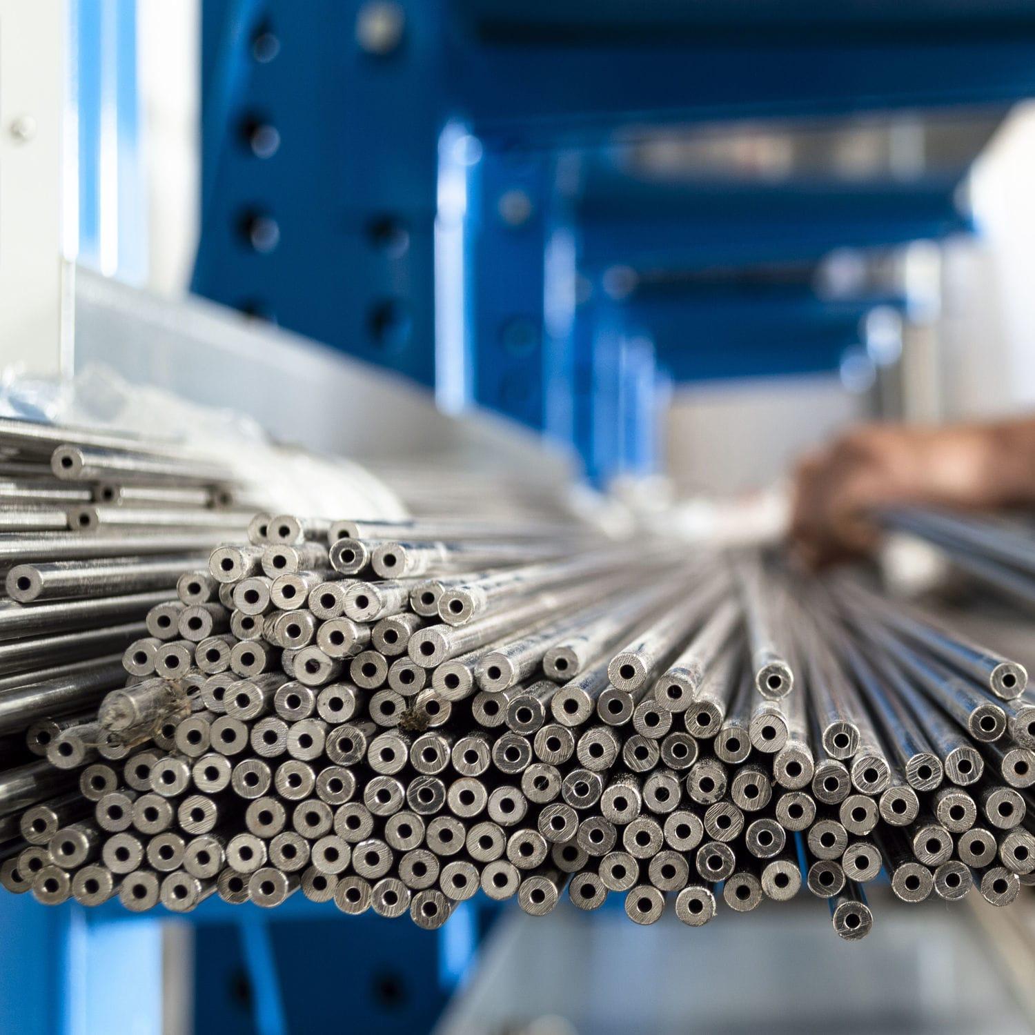 | Stainless Steel Hydraulic Tubes Stainless Steel Hydraulic Tubes Stainless Steel Hydraulic Tubes are engineered for high-pressure hydraulic and pneumatic applications where strength, corrosion resistance, and... View product → |
How installation and routing prevent leaks, contamination and fatigue
A leak often begins at a poorly prepared tube end, not in the straight tube. Cut square with a tube cutter, remove internal and external burrs, and form bends with tooling that preserves the specified radius. Do not force a tube into alignment or weld near a fitting without controlling heat distortion.
Match the tube end, nut, sleeve and fitting body to one connection standard:
- ISO 8434-1 and DIN 2353 cover 24-degree cone connections.
- ISO 8434-2 covers 37-degree flared connections.
- ISO 8434-3 covers O-ring face-seal connections.
A visually similar sleeve or nut from another system will not produce a dependable seal. Tighten each connection to the fitting manufacturer’s torque or assembly procedure; overtightening can damage the cone, flare or O-ring.
Cleanliness must be established before connection. Cap open ends during fabrication, wash out machining debris and preservation oil, then flush the installed circuit until its particle level meets the equipment’s specified ISO 4406 code.
ASTM A380 and ASTM A967 provide recognised practices for stainless cleaning and passivation, but passivation cannot remove contamination trapped in a crevice.
Clamp tubes close enough to prevent vibration without crushing them, and leave room for thermal movement. Support long runs, keep rigid tubing from bridging misaligned equipment, and use a flexible connector or vibration isolation where pump movement and pressure pulsation reach the line. Verify the complete assembly against ISO 4413 and the manufacturer’s pressure-temperature limits.
Frequently asked questions
Where do stainless hydraulic tubes sit in a machine circuit?
They form fixed passages between the power unit, pump outlet, valve manifold, actuators, accumulators and reservoir.
When should you use rigid tube instead of hydraulic hose?
Use rigid tube for fixed, protected runs; use hose where movement, vibration, service access or misalignment requires flexibility.
How do pressure, dimensions and stainless grades affect tube selection?
Check working and surge pressure, outside diameter, wall thickness, fluid temperature, corrosion exposure and the grade’s compatibility with the hydraulic medium.
How do installation and routing prevent hydraulic tube failures?
Use compatible fittings, clean and cap tube ends, support long runs, allow thermal movement, avoid sharp bends and isolate vibration.